The AutoclaveXpress Trilogy turns almost any autoclave or steam sterilizer into a connected, auditable device — with no PC at the bench and no software to install on site. This guide takes you through every physical connection and every setting, in the order you should do them, so that a first-time installer can finish with cycle data flowing to the dashboard. Read it once end to end before you pick up a screwdriver; the few minutes you spend planning will save you far more in rework.
What this guide covers
01How the signal chain works
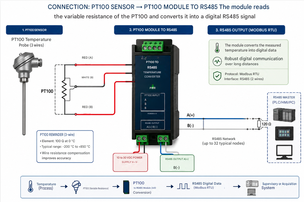
Before wiring anything, it helps to understand the path a single temperature reading travels. The Trilogy is a short, sealed chain of three devices, each doing one job and handing off to the next. Nothing in the chain needs a computer on site, which is exactly what makes the system easy to retrofit onto sterilizers that were never designed to be connected.
It begins at the PT100 probe, a platinum resistance thermometer whose electrical resistance changes in a precise, repeatable way with temperature. The probe does not output a number; it outputs a resistance, and something has to measure that resistance and turn it into data. That is the job of the Lucid485 converter. It energises the RTD, reads its resistance, compensates for the cable, and publishes the resulting temperature as a digital value on an RS485 bus using the Modbus RTU protocol — the same rugged, long-distance signalling used across industrial and medical equipment for decades.
RS485 is reliable but it is a serial bus, not a network. To reach the cloud, those Modbus readings have to become Ethernet traffic. That is the role of the Waveshare RS485-to-Ethernet gateway: it sits on your local network with its own IP address and transparently bridges the serial bus to TCP/IP, so the cloud can read the converter as if it were on the same wire. From there the data travels over your internet connection to AutoclaveConnectPro, which stores every reading, reconstructs each cycle curve, scores it, and presents it on the dashboard with export-ready records.
02Safety & what you need
You are working near a pressure vessel that operates at high temperature, and you are making low-voltage electrical connections. Neither is dangerous when treated with respect, but both deserve it.
The Trilogy hardware itself runs on low-voltage DC, so once the sterilizer is isolated the wiring work is comparable to any RS485 instrumentation job. Have the following on hand:
- The three Trilogy components: PT100 probe, Lucid485 converter, Waveshare gateway.
- A regulated DC power supply matching the voltage printed on each module's label (a single supply can often power both modules if its range and current suit them).
- A short length of DIN rail, or another secure mounting surface near a power source and a network point.
- A Cat5e/Cat6 patch cable to your switch or router, and a free Ethernet port.
- Wire ferrules, a small flat-blade screwdriver for the terminal blocks, and a multimeter.
- Your AutoclaveConnectPro welcome pack with its activation code or QR code.
03Step 1 — Mounting and wiring the PT100 probe
The probe is the foundation of every reading, so its placement decides the quality of all your data. Fit the stainless-steel tip where it genuinely represents chamber conditions — ideally in the manufacturer's measurement port or a thermowell, in the position your validation already trusts. Avoid resting it against a cold wall or directly in a steam jet, either of which will bias the curve.
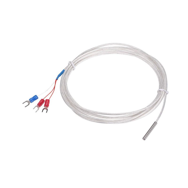
Routing the cable
Run the shielded cable away from heat sources and away from motors, contactors and mains cables, which radiate electrical noise. Keep gentle bends, secure the cable with the supplied ties, and leave a small service loop near the converter so the wire is never under tension. The shielded braid you can see along the cable is there to reject interference; do not strip it back further than necessary.
Understanding the three wires
This is a 3-wire PT100. The third wire is not a spare — it lets the converter cancel out the resistance of the cable itself, which is essential for accuracy over any meaningful length. Look at the spade terminals: two wires share one colour and one wire is a different colour. The two matching wires are the compensation pair and connect to the two terminals that the converter marks as the paired RTD inputs; the odd-coloured wire connects to the remaining RTD terminal.
Do not connect the probe to the converter's RTD terminals yet if it is easier to wire the converter on the bench first — but in most installs it is simplest to land the probe wires now, tighten each terminal firmly onto its ferrule, and give every wire a gentle tug to confirm it is captured. A loose RTD wire is the single most common cause of a jumpy or drifting temperature trace.
04Step 2 — Wiring and configuring the Lucid485 converter
The Lucid485 is the yellow-faced module that turns the probe's resistance into Modbus data. It is built for DIN-rail mounting, so clip it onto the rail first, leaving a little space on either side for the terminal blocks and for airflow.
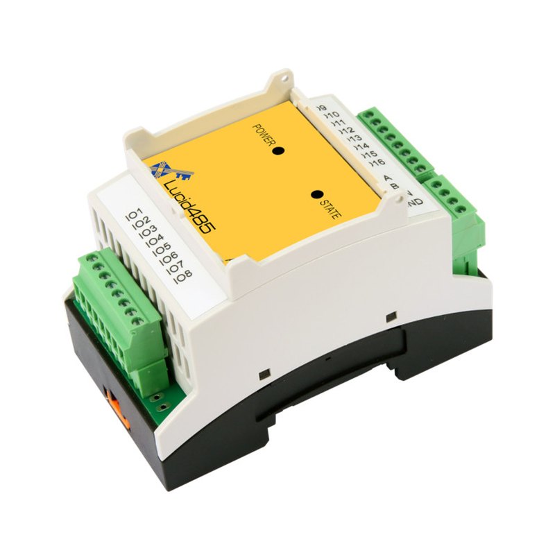
Power
Connect DC power to the converter's supply terminals, observing polarity exactly as printed on the label — reversing positive and negative is the fastest way to damage a module. Apply power and confirm the POWER LED lights steadily. If it does not, remove power immediately and recheck the polarity and voltage against the label before going further.
The RTD input
Land the 3-wire PT100 on the converter's RTD input terminals as described above: the matched pair to the two paired terminals, the odd wire to the third. The converter's printed legend (often near the IO terminals) shows which is which; follow it rather than guessing. Once wired and powered, a correctly read probe should make the converter report a sensible room temperature when you query it.
Serial settings that must match downstream
The converter speaks Modbus RTU over RS485, and three settings have to agree along the whole bus: the slave (unit) address, the baud rate, and the data format (data bits, parity, stop bits). Note the converter's current values — whether set by DIP switches, by a configuration register, or shipped at a documented default. You do not have to change them; you simply have to record them, because the gateway and the cloud will be told to use exactly the same values.
| Setting | What it is | Typical default* |
|---|---|---|
| Slave address | The converter's Modbus unit ID on the bus | 1 |
| Baud rate | Serial speed, in bits per second | 9600 |
| Data format | Data bits / parity / stop bits | 8-N-1 |
*Confirm against your module's label and datasheet — defaults vary between firmware revisions.
RS485 output
Finally, identify the converter's RS485 output terminals, usually labelled A,
B and GND. These three lines carry the data to the gateway in the next
step. Leave them accessible; you will connect them shortly.
05Step 3 — Wiring and configuring the Ethernet gateway
The Waveshare RS485-to-Ethernet gateway is the white module with the RJ45 socket. It is the bridge between the serial world and your network. Mount it on the same DIN rail, close enough to the converter that the RS485 link is short.
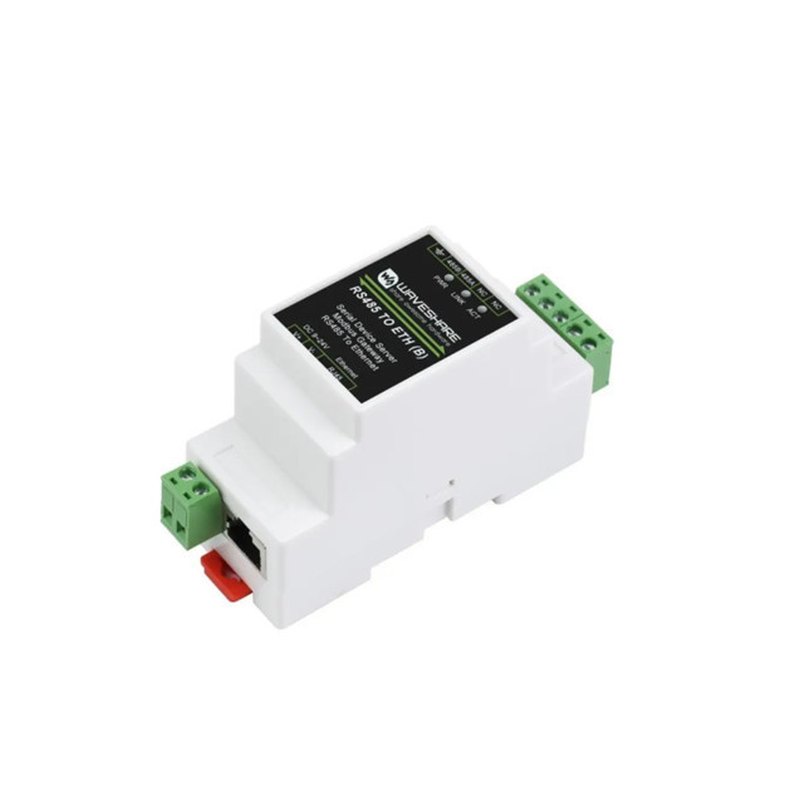
Power
Wire DC power to the gateway's supply terminals, again matching the label's voltage and polarity. Many installs power the converter and the gateway from the same supply — perfectly fine, as long as the supply's voltage and current rating suit both modules. Confirm the gateway's power indicator lights when energised.
RS485 wiring
Connect the converter to the gateway terminal-for-terminal: A to A,
B to B, and GND to GND. The A/B
pair carries the differential signal and the GND provides a common reference; all three
matter. RS485 is forgiving of distance but not of crossed A and B lines,
which is the classic first-time mistake.
A and
B at the far end of the bus stabilises the signal. Add it only if distance or noise
calls for it.The network side
Plug a patch cable from the gateway's RJ45 socket to your switch or router. The gateway now needs an address on your network and needs to know how to talk to the converter. You configure it either through the manufacturer's setup utility (the Waveshare VirCom tool) or through its built-in web page. On a fresh unit the gateway ships with a documented default IP address; put your laptop on the same subnet to reach it the first time, then change the settings to suit your site.
| Gateway setting | What to choose |
|---|---|
| IP address | A static IP on your LAN (recommended) or a DHCP reservation, so the address never changes. |
| Serial parameters | Set baud rate and data format to exactly match the converter (e.g. 9600, 8-N-1). |
| Working mode | The mode that exposes the serial device to the network — typically a Modbus TCP ↔ RTU gateway mode, or the transparent/TCP mode specified in your AutoclaveConnectPro provisioning sheet. |
| Local port | The TCP port your provisioning sheet specifies (commonly 502 for Modbus TCP). |
06Step 4 — Network and internet
With the gateway addressed, place it properly on your network. A static IP or a DHCP reservation is strongly preferred: if the gateway's address drifts, the cloud loses the device. Note the final IP address on the install sheet and on a physical label — future-you will be grateful.
The gateway also needs a path to the internet so that AutoclaveConnectPro can reach it, or so it can reach the cloud, depending on the mode in your provisioning sheet. In most clinical networks outbound connections are allowed by default, but tightly managed networks may need a firewall rule. Share the destination host and port from your provisioning sheet with whoever administers the network, and confirm the path is open.
| Network item | Recommendation |
|---|---|
| Addressing | Static IP or DHCP reservation for the gateway. |
| Segmentation | Where possible, put the device on the network segment your IT team uses for medical equipment. |
| Outbound path | Allow the gateway to reach the AutoclaveConnectPro host and port listed in your provisioning sheet. |
| Documentation | Record the IP, port and physical location for every installed gateway. |
07Step 5 — Provisioning AutoclaveConnectPro
The hardware is now ready; the last step is to introduce it to the cloud. Your AutoclaveConnectPro welcome pack contains an activation code and usually a QR code that ties this gateway to your account.
- Sign in to your AutoclaveConnectPro workspace.
- Choose to add a device and enter the activation code, or scan the QR code from the pack.
- Give the device a clear name and map it to the specific sterilizer it monitors — for example "CSSD — Autoclave 2". Good names are what make a multi-site fleet readable later.
- Enter the gateway's address and port exactly as you configured them, so the platform knows where to read the converter.
- Save. The platform begins polling the converter through the gateway and confirms the link.
08Step 6 — First cycle and verification
Now prove the whole chain end to end. Work through the indicators from the probe outward, then watch a real cycle.
The LED checklist
- Converter POWER — steady on.
- Converter STATE — blinking, showing Modbus traffic from the gateway.
- Gateway power and link — power lit, Ethernet link active.
On the dashboard, the device should show as online and report a plausible idle chamber temperature. If it does, the serial settings, the RS485 wiring, the network path and the cloud mapping are all correct — every link is proven.
Run a cycle
Start a normal sterilization cycle and watch the dashboard. You should see the temperature climb through heat-up, hold across the plateau, and fall during exhaust — the characteristic curve of a real cycle, drawn live. When the cycle ends, confirm that AutoclaveConnectPro has stored a complete record with its curve, timestamps and result, and that you can export it as a PDF. That exported record is the whole point of the system: a load that can stand up to an audit.
09Troubleshooting
Almost every first-install problem falls into a handful of patterns. Work down this table in order — it follows the signal chain from power to cloud.
| Symptom | Likely cause | Fix |
|---|---|---|
| No POWER LED on a module | Reversed polarity or wrong voltage | Remove power; recheck polarity and voltage against the label; re-apply. |
| Temperature jumps or drifts | Loose or mis-paired RTD wire | Re-seat all three probe wires; confirm the matched pair is on the paired terminals. |
| STATE LED never blinks | RS485 not communicating | Swap A and B; confirm GND is connected; check baud and format match. |
| Device offline in dashboard | Network or address problem | Ping the gateway; confirm its IP, the TCP port, and that the address has not changed. |
| Gateway reachable, still no data | Serial parameters mismatch | Make the gateway's baud, parity and stop bits identical to the converter's. |
| Works on the bench, fails on site | Firewall blocking the cloud path | Ask IT to allow the outbound host and port from your provisioning sheet. |
| Reading offset by a few degrees | Cable resistance or probe placement | Confirm 3-wire (not 2-wire) wiring; check the probe sits where it represents the chamber. |
10Maintenance and good practice
A clean install stays reliable for years with very little attention, but a few habits keep it that way.
- Label everything. Mark the gateway with its IP and the sterilizer it serves. A labelled device is a five-minute fix instead of an afternoon's detective work.
- Route and secure cables once, properly. Most long-term faults are mechanical — a wire that worked loose or a cable chafed against a hot surface. Strain relief and tidy routing prevent them.
- Keep firmware current. Apply gateway firmware updates from the manufacturer during planned maintenance windows, not in the middle of a busy clinical day.
- Treat it as a network device. Keep the credentials strong, keep it on the right network segment, and include it in your asset register alongside other connected equipment.
- Glance at the data. The earliest sign of a failing heater or a tired pressure sensor often shows up as a subtle change in the cycle curve long before a cycle fails. The dashboard is most valuable when someone actually looks at it.
That is the whole chain: a probe in the chamber, a converter that turns resistance into data, a gateway that puts it on the network, and a cloud that turns it into records you can trust. Once it is running, every cycle is on the record — automatically, on any autoclave or steam sterilizer you choose to connect.